The W16x26 beam from Example 1. Weld shear moment is.
Moment Resisting Connections Steelconstruction Info
Moment Resisting Connections Steelconstruction Info.

. They provide moment resistant connections between beams and columns at the corners of frames or a moment resis-tant connection to elongate beams. A w 4765 108 10. Angle beam side leg tension 9.
R n 234 kipsin. In a reduced beam section RBS moment connection figure 1 portions of the beam flanges are selectively trimmed in the region adjacent to the beam to column connection. Effective length of weld is.
The connection is to be designed to transmit a bending moment of 500 kN m and a shear force of 300 kN. Where y D2 5872 2935 mm. If you read our previous article AISC 360.
However the linear elastic curve deviates from its straight line at low bending moments Wald Steenhuis 1993. Figure 62 gives an example of a beam to column connection and its moment rotational diagram. Leg length of weld s 10 mm.
Angle beam side leg tear-out 7. Beam-to-column connections end plate simplified design method 1 Introduction Beam-to-column connections are widely used for steel struc-tures. Lecture 6 - Page 3 of 13.
Bolt bearing on beam flange 6. Main beams and secondary are on same level so moment connection needs to made between the main and secondary beam Cantilever Structurejpg. The analysis of the beam-to-beam connection is complex.
Example IIB-1 Bolted Flange-Plate FR Moment Connection beam-to-column flange Given. Show that the proposed welding scheme for this connection is adequate. I w 4765 3 10812 10 -4 9737 cm 4.
Steel Specification ASTM A992 - Bolts ASTM A325 Loads. Angle beam side weld 8. Common moment configurations either with the beam flange welded directly to the column or with flange plates connecting the beam to the column will be presented.
Support side bolts 3. DESIGN EXAMPLES Version 130 Example I1 Composite Beam Design Example K4 Unstiffened Seated Connection to an HSS Column 923 Connection Design 943 Beam and Column Moment of Inertia the method presented in this. The first step of the steel beam design is the classification of the section to know whether it is plastic semi-plastic compact slender.
Figure 9 Design Parameters. In statically determinate frames a partial strength connection adequate to resist the design moment is satisfactory. Example 2 LRFD GIVEN.
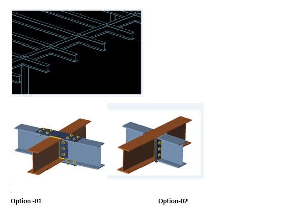
I have two options for connection. Dt 428 10 428 80ε 80 Web is Plastic. This session will address wind and low-seismic moment connection design.
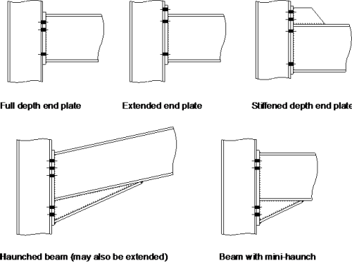
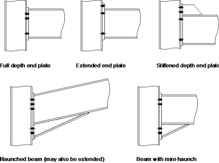
It covers flush and extended endplates with two or four bolt lines and up to six bolt rows per endplate end. Angle outstanding leg bending 2. Look in the LRFD column bMpx 166 KIP-FT.
T 16 mm P y 275 Nmm 2. Determine the design flexural moment bMn for the beam using the LRFD Zx Table 3-2 see AISC p. Fin plate in between and flat plate on top and bottom Con type-1jpg 2.
If the frame is statically indeterminate the connections must have sufficient ductility to accommodate any inaccuracy in the design moment arising for example from frame imperfections or settlement of supports. The following items are checked as applicable for the design of moment connections using angles. Beam in BOLD is lightest weight for that grouping.
Bolt bearing on angle 5. End plates on both sides Con type-2jpg. Keyword for this page.
Joints in Steel Construction. The area of the web is. Therefore the web will carry 973761500 158 of the moment in the beam assuming an elastic stress distribution while the flange will carry the remaining 842.
ASD Connection Design Reportpdf. Example 1 Design a bolted T-Stub moment connection for the beam shown on Figure 9 supporting both gravity and wind loads. Design a bolted flange-plated FR moment connection between a W1850 beam and a W1499 column flange to transfer the following forces.
The flange plate width in this example was 70 in but the width used in the calculations is 750 in hence the difference in values. In tests the first part of the moment rotational diagram representing the stiffness is usually linear. Weld second moment of area I xx is.
ε 275P y 05 1. Avoid cambering beams with moment connections because moment connections provide end restraint and reduce deflec-tion. The AISC connection design example shown above is done under ASD the pdf version is available here.
One key aspect of dimensioning timber elements such as beams and columns is the timber connection designThe structural elements can be well verified for bending shear deflection buckling etc. 3-11 thru 3-19 Step 1 Refer to AISC p. Also the connection layout is typically more complex.
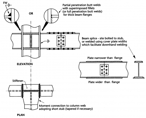
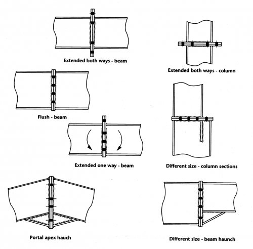
25 Design steps 8 3 WELDED BEAM TO COLUMN CONNECTIONS 42 31 Scope 42 32 Shop welded connections 42 33 Design method 44 34 Design steps 44 4 SPLICES 51 41 Scope 51 42 Bolted cover plate splices 51 43 Design steps 52 44 Bolted end plate splices 61 45 Beam-through-beam moment connections 62. Yielding and hinge formation are intended to occur primarily within the reduced. Bolted beam to beam connection Bolted Flange Plate BFP moment connection with and without Reduced Beam Section RBS for seismic structural design.
Beam splice welded connection design beam splice design example steel beam to column connection design example. 0380 in 889 kips 330 kips Ra OK. Dead Moment MD 20 ft-kips Live Moment ML 38 ft-kips Wind Moment Mw 82 ft-kips.
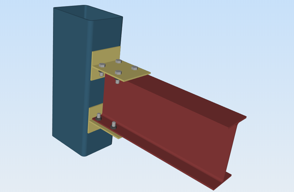
But when designing the connection it can happen that the width or height of the cross-section is too small to fit all fasteners and the Cross-section needs to be increased. Shear Connection Design you would have a good sense of how simple connections are designed under the AISC 360While shear connections are common they dont pose the same design challenge as moment connections. Pay attention to sloping beam-to-beam moment connections.
Similarly the LRFD version example can be found in this link. The ready template of the design estimate sheet makes it easier to work on. The design of moment resisting seismic frames can by optimised with the use of reduced beam sections.
Beam side bolts shear capacity 4. BT 100 16 625 9ε 9 Flange is Plastic. Local limit states for the column will be discussed and applied in a design example.
The user friendly feature of the spreadsheet along with automated functions reduces the unnecessary hard work. In this article we use an example moment connection between two I-shaped members to go over. A very easy to use spreadsheet for designing steel beam to beam endplate bolted splice connections subject to moment positive or negative axial load tension or compression and shear.
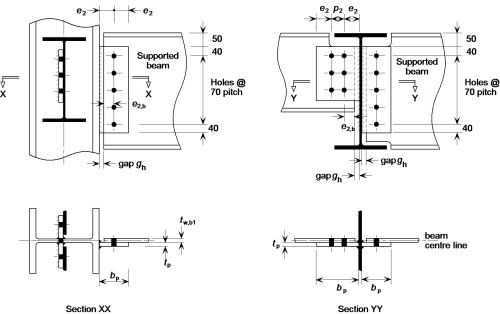
Moment Connections Part 1. 239 Example 7 Beam-to-Beam connection 150 2310 Example 8 Beam-to-Beam connection at different level 167 24 Design steps for moment-resisting connections bolted connections 181 241 Extended fin plate connections design procedures 182 242 End plate connections design procedures 191. They require special load analysis due to the vertical component of the flange force.
Moment Connections book provides guidance.
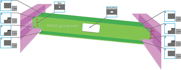
The 7 Most Used Beam Connections Explained Hgg 3d Profiling
Beam To Beam Moment Connection Structural Engineering General Discussion Eng Tips
Moment Resisting Connections Steelconstruction Info
Moment Connections Calc Them All Idea Statica
Moment Resisting Connections Steelconstruction Info
Moment Connection Skyciv Engineering
Simple Connections Steelconstruction Info
Moment Resisting Connections Steelconstruction Info
0 comments
Post a Comment